
1955 Ford Part 21: Overdrive Transmission, Door Dolly, and A/C Trouble
- Hot Rod Reverend
- Oct 2, 2017
- 13 min read
Updated: Dec 27, 2019
(Note: You are reading the progress from a project that began in August of 2014. This information in this post was originally dated in May of 2017.)
Overdrive Transmission, Door Dolly, and A/C Trouble
Last week I picked up this free Rack Cart - it has metal shop casters, is quite sturdy, and will be used to hold the doors once I remove them from the body. Obviously I plan to modify this unit a tick because I will need to figure out exactly how I want to mount the doors for access and stability but it looks like it should not be too difficult to figure out.


And then there was last night when I finally wired up the AC 100% (except for the compressor of course, but the wiring is there just disconnected) and turned on the evaporator unit to see what kind of volume of air I would get out of the thing. If it holds up it looks like it will turn out a good amount of air. Of course the last thing I would need would be refrigerant, R134a. I stopped by Autozone and it was $13 a can. Went to Home Depot to see what they had for courtesy light idea under the dash and wouldn't you know it but the refrigerant was on sale for $10 a can. Beyond that, the utility lights pictured rang up at $.01. That's no typo - look at the photo too, $.01 !!!


Sometimes it falls into place, other times... it doesn't!
(a week or so later...)
Boy what a fun day we had! I have been out of town for a while but it looks like the "Ford Follies" show has returned. It all started at the post office. After being in Canada for about a week or more, we had our mail held and delivered... well we thought it was all delivered. I had to go to the post office and pick up three packages. One was a father's day present for my dad, the other was a new key/cylinder set for the 55 trunk and doors, and the other was a box of 6 cans of R134a (yep - I returned the Home Depot special - these 6 cans were much cheaper and the same brand). http://www.ebay.com/itm/282046970166?_trksid=p2057872.m2749.l2649&ssPageName=STRK:MEBIDX:IT The guy behind the counter at the post office was having a rough day - according to the website reviews and complaints registered this fella is always having a bad day. After my request to receive the mail he slapped down a few pieces of junk mail (which we had already received paper mail so I have no idea what this was about) and the package with the key/cylinders set. He finally decides it best to go get his supervisor. 15 minutes later my other two boxes miraculously show up. Fun times. So... we get home and it's time to fill this AC system with oil and refrigerant and... "Oil? did we get oil?" I muse to myself. Uh... and out to the parts store. So... we got the oil, we got the refrigerant, we got the can tap and we are READY.

First up was to hook up the vacuum and let that run for at least 45 minutes (I actually ran it for almost an hour while getting some other things done today like some body work on the hood.) I was surprised how quiet the pump is - it never got that loud. The gauges looked good again and we were holding a good vacuum on the line without the pump (like before when we did a test run). Here is a brief video as well:
Ok so the compressor was turned about 20 revolutions to move the oil through the reed valve, and we got out a can and hooked it up. It only took about 10 seconds for me to hear a "hissssssssss........"
"What in the world? This thing was holding a good vacuum! Close the valve quick and find that leak!"
When I found the leak I had to remove that section of line from the car and take it to the bench to re-crimp. When I got that done I reinstalled the line and fired it back up to load the refrigerant through the manifold. Hey! We got it going now - the clutch is engaging, the air is cooling, and we are on our way to... What's that hissing sound? Yep - another leak. On the high side of course. By this time I am on my second can of R134a and I don't want to remove a section of line because of what I will lose. What can we do?

Take the crimper to the line and finagle a way to get it recrimped while still installed. Don't ask me how, but it worked and we were on our way! I loaded up that can and started watching my gauges as we were starting to get close. We were not quite there after can number 2 and so we tapped in to can number three. Good deal - the AC is humming along, we aren't leaking anything, no squeals or what have you and the gauges are good. Successful job I'd say, let's shut this thing down. Now to get a drink! (come back a few minutes later....)

Are you kidding me? Here is the video evidence of the disaster:
If you are with the EPA, I have no idea where this car and garage are located. Obviously the high pressure (about 200 psi on the Hi side) overcame the crimp job I did on that particular fitting. So... off she came and we did a re-crimp on another section of line. I cannot understand why if a vacuum held like it was supposed to why there was all this issue with leaks. Of course the vacuum goes one way and the hi pressure goes the other but this was getting ridiculous! All is well that ends well. I feel like I wasted a lot of time correcting my own errors but there you go - Ford Follies in action. I did get the heater core lines run and another coat of primer on the hood so all was not in vain I guess. And, we do have cold air in the car!

(a few days later...)
Got a few things done yesterday - the best of which was a brake light switch install and test. Here are some details on the bracket... I used 16 gauge sheet metal reinforced a little with some welding. The switch is a generic plunger I picked up on eBay.


It took just a bit to fabricate, my welder was turned up too high so I blew through the first tack pretty quickly but it dialed in nicely and I added a small triangle to the return that holds the switch.
I finally got around to installing the firewall cover plates that surround the steering column. This was a little more involved than I thought it would be what with the clutch rod and the seal. First up was to align the rubber seal to the holes on the firewall.
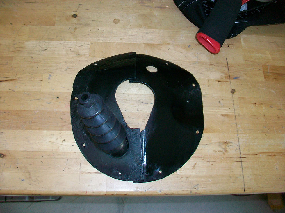


You can see I pulled the speedometer cable through just to be sure of alignment. I also used a dental pick to align the holes on the firewall to the holes in the rubber seal. Two slits were cut for the clutch rod seal to go through and we began installing the driver's side plate first. There are 9 total screws, and the two at the very top are installed from the engine bay through the firewall while the seven other screws are installed from the interior through to the engine compartment.


The clutch rod seal was pretty pesky. It was difficult to install on the sheet metal plate so I decided to leave it on while pushing through the seal and screwing the plate to the firewall. It obviously pulled the alignment through so I had to readjust that. After it was all aligned, I installed the screws loosely so that the plate and rubber seal could slide a little bit until both sides were installed.


That clutch rod seal was very tight. I could not get the clutch rod through the seal without it popping off of the sheet metal plate. So... it was over to the bench to pry and tug and work the end through. After that we reinstalled the clutch rod and things were made ready to go.
Disaster struck again... While getting things together for the OD cable I happened to notice serious oil leaks at the transmission. The small seal for the solenoid was actually torn and would not hold its seal, and the the OD adapter on the case was leaking at two separate places, and the cover plate for the shifter forks was also barely seeping.


More on this later but for now let's look at the OD cable. (yep, you can tell from the photos below that I pulled the shifter and brackets that attach to the transmission) These photos show me trying to make sure the lever works appropriately with the cable pull and that there is little to no play with the movement.


Overdrive engaged below: well, kind of - it won't actually engage unless you are above 28 mph, but at any rate this position means that it is ready to engage.

Overdrive lockout below: it will not engage for anything, and for all practical purposes you only have a standard transmission with regular gearing.

Of course at this point for me, this is all sheer conjecture because I have never driven the car while having the OD hooked up and ready to go. The standard transmission did shift just fine and worked well the summer I installed it in 2015 and moved the car around quite a bit in a very large parking lot. Before we start looking at this transmission (again) let's take a look at this:

YES! Color on the hood! Can't wait to shoot some clear coat. Ok, now on to the transmission . First I had to drain it. I filtered the old oil since it was basically unused, and I stored it in a clean jug marked appropriately:


Then I got my jack, unscrewed a "few" fasteners and bolts (don't you like the one bolt/nut combo at the crossmember where the bracket for the E-brake attaches to the frame??? Aaaaaarrgghhhh!), and dropped her down gently to the floor:

Once it was on the bench it was time to pull that pesky seal and install a new one:


I will have to say that after wrestling with all of the hardware to remove the transmission, messing with the oil, etc, I was not looking forward to knowing that it was indeed tear down time - AGAIN. I guess this is the way you learn and in the future make sure you concentrate and do right the first time. But, the shifter brackets did need to come out because they had to be painted, the cable routing was done (pics on that later) so it was time to pull some stuff back, I wanted to trim some of that sheet metal around the shifter to ensure a good fit, blah, blah, blah. All of that still did not help my attitude. After I removed the cover plate that hides the shifter forks, I saw this:

The oil was already puddling down near the lower corner and was ready to give way. At first I wondered why that was the only area showing oil on the gasket. Once I removed the gasket though I noticed that the pin that secures the countershaft in place WAS NOT DRIVEN FLUSH with the case. Therefore the cover could never fully meet the surface of the case itself and a good seal just would not happen. MISTAKE TWO in this process! The picture below shows the pin driven below flush so as not to cause further issues.

We turn our attention next to the rear of the transmission and the OD adapter case. This is held to the transmission in four places and they all have 5/8" heads - eazy breezy. However, before you fully disengage keep in mind two things. 1. There is a pin that must be removed - if you don't do this you will never get the case to separate completely. The pin is this small:

and it is placed here, driven in from the top of the casing. The picture from the bottom:

and from the top:

The pictures above show the boss for the lever/shaft that operates your engagement of the Sun Gear (well, provided the pawl from your solenoid engages also, but we will talk about that more later). At any rate, once the pin is removed, you need to pull the shaft out as far as it will go. (Don't worry, it won't completely fall out - it is actually inserted from inside the case.) Ok, so that is number one. 2. Once you remove the rear casing there are a number of small rollers that will drop out and you will hear them plunking all over the place. Don't lose them! You need each one and they are a specific size, etc. Look at this photo below... few of the rollers have already dropped into the tailhousing.


There is a large clip that keeps the rear shaft in place in the tailhousing, but we will talk more about that later - for now, just know that the clip is secure - it ain't coming out. Later on for final reassembly you will find that it is a real pest. Continuing with this transmission assembly, the next item up was to remove the small stud - it is a press fit and it keeps the shift rail i position - and then remove the large metal spring clip that keeps the pawl assembly in the adapter. Of course the actual pawl must be remove as well.

Once you remove the U shaped clip from the end of the shaft, the sun gear assembly just slides right off.

Next up is to drive out the shaft that the countershaft gears ride on. You drive it out from the front of the case here:

note the shaft seated at the lower left of the snout - it is 3/4". After the countershaft drops to the bottom of the case (and your needle bearings - keep track of those!), the rest of the gears can be removed by simply unbolting the adapters and sliding the particular assembly out. The snout will have a number of rollers inside of it - keep track of those too! Everything but the reverse idler gear was removed.

We will take some time out here and just note that for this refresh I used better gasket material than what came in the kits. It was not too difficult to cut my own and the bolt holes were punched with an old socket.

Ok, so back to the gears. The first thing I needed to do was secure a 3/4" dummy shaft of wood to use for the countershaft assembly. This was installed in the sleeve, the sleeve and dummy shaft were placed in the countershaft assembly, and both sides received the 22 needle bearings. Do not forget to put your small washers on either end!


Next up was to prep the snout by putting all of the rollers back in. A "little" grease helps with this because you don't want anything falling out while you are sliding it back onto the main shaft.


Then I checked to make sure it would slide on like normal...

Now back to the main case. The countershaft was placed inside first, with the one large washer at the front and two large washers at the rear. For now we just let them slide into position and sit there. Later on when we raise the countershaft to meet the main shaft we will make sure the washers are lined up to pilot holes.

After that we fit the main shaft and adapter assembly to the main case, making sure the gasket was sealing nicely. Then the snout and its adapter (with a good gasket and sealer) were slid into position and bolted down. Now we will show you why we need that dummy shaft sitting in the countershaft assembly...

Raise the countershaft assembly into position, checking your dummy shaft reference to the pilot holes on either end at front and rear, and checking your washer locations. It is tight for sure but still doable. Once you are in position, you can begin tapping the metal shaft entering the main case at the rear like so:

As the shaft goes into the case it will push the dummy shaft out:

Along the way as you get ready to flush up the shaft with the case, you will want to pay attention to the rear of the shaft and the small hole seen here:

This will need to align with the pilot hole in the main case that traverses the case perpendicular to the countershaft (remember the photo from before where this pin was not flush with main case, causing a leak?). If this small hole is not lined up properly you will never get the pin to go through.

As you can see above that pilot hole for the pin traverses the length of the case from side to side so that when you full seat the axle for the countershaft you can make sure it is oriented correctly.

From the rear you can tell that I had to use some washers to help keep enough pressure on the adapter so that the gasket and sealer would keep things tight. Obviously this was removed when the tail housing was installed. You can tell from this picture though that the axle for the countershaft can be seen/accessed here at the rear of the case even with the OD adapter installed. We are almost done - I have not alluded to the main case cover that seals up the gears and orients your shifter forks but this should be pretty standard I would imagine. Just make sure that pin is driven flush, or below, the main case pilot hole.

From here I decided to put the transmission on end so that we could place the tail shaft and tail housing on without much issue. The old Black & Decker Workmate came into play here. Once the transmission was in position we went in reverse order of disassembly and installed the pawl and its mechanism and the large clip. From there we put the sun gear assembly back on with the lockout slide/stud in position too. Don't forget the U clip that keeps the assembly on the main shaft! Also, I elected to use a copious amount of bearing grease to keep all of the rollers in position. Some fellas use rubber bands to keep them in position. I double checked all of the work leading up to the installation of the tail shaft and housing and prepared a gasket. From there it was simply a question of how to get that large clip to expand enough for the housing to slide over the tail shaft.


I probably should have taken a few more photos but I would imagine that good manuals show the same idea. The best thing to do is to take the tail shaft out of the housing, install on the sun gear full seated, and then take your tailhousing and slide that on the whole works. You will need to work with the large clip that is basically a keeper for the tail shaft itself. The clip can be accessed by removing a small rectangular plate on top of the housing. Spread the clip and the housing will go the rest of the way. The clip basically surrounds that main bearing on the tail shaft and is kept in a small groove on the bearing's circumference. Once that was sealed up, I reinstalled the lockout lever on the exterior of the tailhousing. While I did not refer to it, the small shaft here needs to meet up with the cutout that is on that lockout lever slide on the inside of the transmission. This is key. there is also a spring in the tailshaft that you need to make sure is oriented correctly because it is used to help with this slide. Once the lockout lever shaft was seated back into the housing, I tapped the small pin back in and attached the lever correctly.

Here she is, ready to be re-installed. And this time hopefully without leaks!


Comments