
1955 Ford Part 56: Speedometer and Odometer Reset
- Hot Rod Reverend
- Jul 14, 2018
- 7 min read
Updated: Dec 27, 2019
Speedometer and Odometer Reset

Back in May the car proved itself very roadworthy. After that weekend of a few short runs and a "proving" of several components the old 55 was unfortunately put into the garage for several weeks to remain untouched. This summer has been the busiest I have ever had for my life calling of God to work with churches and their ministry to children. Meetings in California, Florida, and Pennsylvania dominated the schedule and the time to work on the car was just not available. I even missed a Y Block drag race weekend at a local track here in the Cincinnati area. However, I did find time to have the car officially titled and registered here in Ohio. The Fairlane is now legal with a regular plate (stayed away from antique tags for now) and it is fully insured.
The 1955 Ford may look like it's finished, but remember from my last post that we were in a hurry to get it back on the road for my daughter's graduation so there were many finishing touches missing. For instance, there are no mirrors on either door, the kick panels have not been installed, the heater control bezel and plates were secured but the levers and cables were left out, and on and on it goes. The most recognizable issue - the speedometer cable was not installed yet!

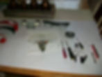
However the biggest problem I knew about is pictured above. The bolts and nuts that attach the control arms to the frame had not been torqued! Now, I had remembered this back in May when we were in a rush but I knew they were secure and we would only be driving a short distance. So, first up on the list of work to be done was actually the torqueing of the bolts. There are four, and the shop manual has good charts that show the specifications. I keep a rough one around in the garage that I don't mind getting a little grease on now and then. I only paid $10 for it a few years back. The main reason that these bolts were not yet torqued was that this process is not to take place unless the full weight of the car is resting on the suspension. I also torqued the front stabilizer bar while I was under the car with the torque wrench. To my surprise, both the control arms and the stabilizer bar needed their hardware to tighten up at least an inch to come into specifications with the proper torque load. To me that sounded like we had things loose, but if so I could not tell. The test drive after the work really showed an improvement in the car's handling.


I also changed the oil while I was at it underneath the car since it had been over a year. Note the bottle of Lucas Oil Additive. Everyone has their formula and elixir for classic car engines and this happens to be mine - 4 quarts of Rotella 15w40 and 1 quart of Lucas. With all the Y blocks I have built over the years this oil mix has worked well for longevity and wear.


And yes, from the picture immediately above you can tell that I use a creeper from the 50s - works well for me!
After all of that work was complete it was time to start removing bits and pieces of the dash. First to come back out/off was the radio delete plate (I have actually found a modern radio - a marine version - that will fit the round hole and bezel, but more on that in another post). Then the heater control plate and bezel along with the speedometer/odometer assembly were removed. I also removed the speedometer cable from the transmission.
The 1955 Ford passenger car speedometer assemblies are pretty straightforward. The only difficulty really is in trying to remove them from the dash when all of the other accessories, wiring, etc are all installed. You literally have to lay upside down to remove it, and some fellas even resort to removing the front seat to do so. Our plan: disassemble, clean, inspect, and re-install the entire unit back into the car. However, I also desired to reset the odometer back to "0" just for kicks since we had worked so much on the restoration and since the title reads that the mileage is in excess of mechanical limits.

A brand new jewel kit was delivered and I set about installing the new colored disks and washers. I already had good bezels that I polished up with Brasso and steel wool. The front piece ended up looking pretty good.

The jewel kit also contained the disks for the "Gen" and "Oil" lights. These were the old ones that I removed from the gauge assembly:

Over the years the bulbs for the idiot lights had done a number on these thin, plastic pieces.

The business end of the speedometer and odometer mechanisms was really what I was after, so we turned our attention to more disassembly and inspection.


To remove the odometer roller assembly from the unit, the small clip pictured above had to be removed. The rollers were in good shape, and within a few minutes I had reset the rollers to read "0's" all the way across.

If you take note of the picture immediately above, you can see that I was testing to find out if I had the orientation correct. Yep, you guessed it, I was one row too low! I had reset the row of 9's up above to 0 to match the odometer window in the metal housing!
Pictured below is an important part of this process. You can see that a small brass plug was removed to gain access to an oil passage where a wick is in place. This wick was in good condition and after cleaning the assembly I re-oiled it with mineral oil.

Every metal piece was cleaned with thinner and then all of the moving parts were oiled before re-assembly. Below is a video of test run I made with my drill. (No, I do not work for a used car dealer!)
Of course, no speedometer or odometer works well without a good cable to feed the rotation of the transmission to the gearing in the assembly behind the rollers. The procedure I used to clean and lubricate the speedometer cable is as follows:
1. Remove the Cable Assembly from the car.
2. Remove the inner cable from the housing/liner (inner cable looks like a thin, flexible wire).
3. Clean the inner cable and the housing/liner (I flushed with thinner and with Brake Clean aerosol spray)
4. Inspect for kinks, wear, or any other problems.
5. Spray Graphite lube into the housing/liner.
6. Re-install the inner cable into the housing/liner and check for proper lubrication.
7. Use the actual transmission gear to spin the cable in the housing/liner.
8. Re-install the Cable Assembly first into the transmission then the speedometer


The pictures above show the condition of the cable upon removal. The first picture is the end that goes to the transmission and of course the picture immediately above is the end that secures to the speedometer. I did have an issue with the gears in the picture below:

I could not remember which one to use! And to be honest, I did not remember which gear came from the Fordomatic originally, which gear came with the 3 speed that I rebuilt, and whether or not either one of these two came from either transmission (I have parted quite a few.) In the end it does not matter. Since I changed out the transmission, have what looks to be a little different size tire, and especially since I switched the rear end to a 3.78, there is no telling which gear I will need to give an accurate reading for the speedometer. It will be a show I am sure. The two gears above have different teeth counts - one was 19 and the other 21. Parts suppliers have a full range from about 17 to I think 23 or so. This is all because of the different configurations that Ford produced. It will have to be trial and error I guess.
The gear was fitted onto the inner cable to check for rotation and wear. All things looked good.


I was sure to clean the threads too since the Cable Assembly is best secured by hand - clean threads mean a good fit anyway. Here is a photo of the spray can of Graphite Lube I used for the cable assembly.

I will be sure to let you know the results. I mulled over the lubrication issue for quite a bit, read several articles and watched a few videos. After all of that I came to the conclusion that Graphite was the way to go.


Now that all seals were new and things tightened up, getting the Cable Assembly back up into the car and under the dash was trying. The entry point for the cable is in a hard-to-reach area. You can see in the photo above that there was a small hole left over, even in the rubber. I sealed it up with the 3M Strip-Calk. By this time I own stock in 3M!


The two pictures above show an important facet when putting a car back together after there has been so much painted - if you want your wiring to work right, MAKE SURE YOU HAVE A GOOD GROUND! The photo immediately above shows where the turn signal socket is installed. The socket is one wire and is grounded by the body of the assembly. I had to file back the paint all around the circumference of the hole so that we had good electrical contact.
After all of the wiring was finished, I made a video about the results. Let's just say this now, I have some sleuthing to do if I am to figure out what is causing a very weird problem!
If that discovery was not fun enough, I have also found out that my AC is on the fritz for some reason. I really think the expansion valve is bad - there is no cold air out of the evaporator even though the compressor is doing its job. The main issue that makes me think expansion valve is that the compressor is showing 275 PSI on the high side and 0 on the low side. Something is blocked somewhere. Let's hope I can get that fixed. We are in triple digit heat right now!
I am in the process of working on the heater controls and I have them almost ready to install. More on that later...