
Setting up a Temporary Shop, Upgrading the Air Compressor, and Upcoming Projects!
- Daniel Jessup

- Oct 15, 2022
- 10 min read
Updated: Apr 5, 2024

One small copper line from the air compressor was replaced by quite a bit!
The last blog post briefly mentioned that we have moved into a temporary location while I sort out our next direction in life and church ministry. Unfortunately such items as my Ohio driver's license and a few other credentials have come up for renewal during this interim period. That may not sound like a big deal, but when church congregations in other states are having conversations with us about potential pastoral work, at times it is easy to believe as though you are going through motions and encountering red tape that you will be once again experiencing within a few months. And indeed, that just may be the case. Along with the tedious work of boxing up parts, tools, and supplies for temporary storage comes the ever-present temptation to keep things going in the garage. I just cannot "sit tight" for a few months.
Initially, I purchased quite a few of those tool storage containers on wheels, an embarrassing amount of shrink wrap, and even loaded up 3 or 4 pallets of mid-50's Ford parts in the office warehouse. Even though the holding pattern in life puts me in a quandary, the "wrench-turner" side of me cannot leave well enough alone. Maybe it's in my DNA, maybe it's just become such a part of my life that I can't go a few months without opening the tool box, or maybe it's the best way for me to unwind what with the busy schedule and all. Whatever the case, I have made the decision to set up shop.

The 60 gallon, upright, 5hp air compressor has served me well for several years.
The heart of my shop is the air compressor. The unit I own has been quite a workhorse over the past several years, and if you have been reading over the blog posts any length of time you are aware that my setup for air lines and drops in the shop are very traditional. In the last two garages when I installed an air compressor and all of the lines, I used standard 1/2" gas pipe to carry both the pressure and the volume to various air tools or paint guns. All of us know that for all the wonderful work that can be accomplished by an air compressor, there is one clear and present danger to air tools and paint guns alike - moisture. As the compressor pump brings in air to the tank, there is quite a bit of heat generated. Moisture in the tank will drop to the bottom and therefore to the drain as the air cools (compressor manufacturers recommend draining the tank daily). The more the compressor runs, the more air that passes from the tank to the lines and the drops, the more air the more moisture, etc. The main reason I have used cast iron gas pipe is that the further the air moves along the piping away from the tank, the more the air cools. The more the air cools, the more that good old H2O will go from a vapor to a liquid state. In essence, the longer your pipes run and the further away from the tank that you place a water separator/filter, the better filtration of water and other contaminants you will have. All of this means that you will be continually receiving a supply of cool, dry air for your tools.
Once we moved into this temporary housing situation, I believed I needed to get my air compressor up and running but really did not want to take the time to measure out, install, and then tear down more than 80 feet of cast iron gas pipe when I move permanently. There are options such as industrial level air driers (like AC units for air compressors), quick connect kits like Rapid Air, and others, but I believe I found the best option. Enter the aftercooler!
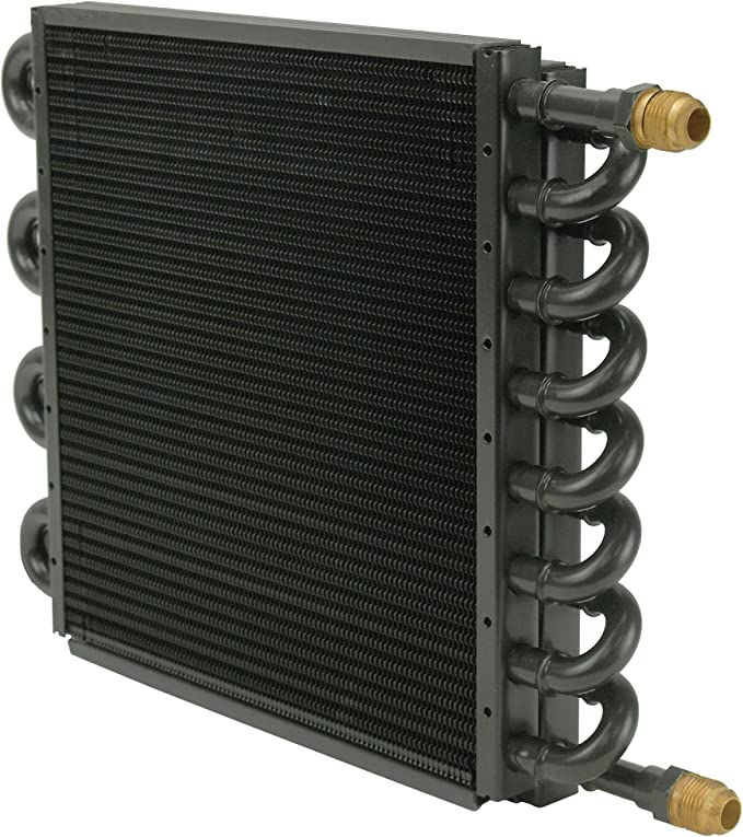
The Derale 15300 cooler is normally used for oil or automatic transmission fluid applications.
I would imagine that every reader of the blog understands the principle of a dedicated, finned, cooler like the one pictured above. The most obvious of which would be the radiator that many 4 cycle, gasoline engines have under the hood. Heat from the engine coolant passes through a series of finned cores (usually with forced air passing over those cores and fins) to effectively lower the temperature of the coolant as it moves through the unit. A quick online search would yield quite a few online resources that would lead you to believe that this same core from Derale can not only be used to cool liquid but also air.
Most would probably assume that the core should be installed in line at some point between the tank and the drops. However, the best position for an aftercooler like this (essentially a heater core) is between the pump and the tank with a water separator at the lowest point in the lines so that gravity can ensure that the water drops out through the separator's drain.
As is my custom, I did make a quick video that shows a little more detail, the two problems I encountered, and the end result. The video link is at the end of the post.
To walk you through the process, the first thing you will need to do is to purchase an aftercooler. It does not have to be the Derale unit, but the size of the 15300 is very good, it's made in the USA, and is readily available on Amazon, eBay, or even auto parts stores. I paid approximately $70 for mine. Beyond the simple purchase of the cooler was also the acquistion of quite a few AN, NPT, and compression adapters and fittings. If you plan to tackle a job like this then certainly much of what you need to buy will depend upon the size of your feed line. (the line from the pump to the tank) Bear in mind that the Derale 15300 has a fitting size of 8 AN.

1/2" copper pipe, compression fitting, olive, compression to NPT adapter, NPT to AN adapter
To give a little more detail on what I purchased, the following list is submitted:
Derale 15300 aftercooler
1/2" type M copper pipe
AN adapters
NPT adapters
Compression fittings/adapters
NPT brass pipe, coupler, elbow
Water separator (1/2" inlet and outlet"
Electric radiator fan mounting kit
Teflon sealant tape
The most difficult part of the experience had to be bending type M copper pipe. For this purpose I used a manual EMT conduit bending tool. At times, I was able to bend the angles and measurements to what was needed and set the pipe into position without much fanfair. Still other times were an exercise in futility as the copper either crimped, waffled, or just plain collapsed when I tried to get the arc I needed. At one point I did break out the propane torch to heat the pipe before bending which seemed to help quite a bit.
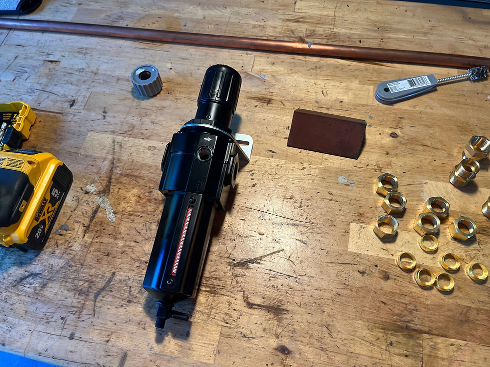
Be sure to check the directional flow of air through the water separator.


Angle iron was cut, drilled, and tapped to mount the water separator.
After I had gathered all of the hardware, the aftercooler, and other items I needed, the first line of business was removing the existing copper pipe that fed the air from the compressor outlet to the tank inlet. The plan was to reuse this pipe to run the air through aftercooler, and then fabricate new copper pipe from the aftercooler to the tank inlet.
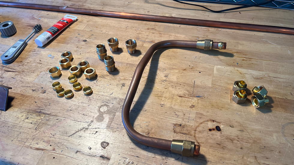
The original plan was to reuse the existing copper pipe that fed the tank.
After removing the line, I mounted the water separator to the angle iron bracket that I had installed on the air compressor motor mount. Next, I fabricated a new line from the water separator to the tank inlet. (Note: in the video you can see where I had to lower the mounting of the separator 1" because of my limits on pipe bends and not being able to bend less than 90 degrees.

The compression union fitting helped resolve my mistake!
I have to admit I got into a bit of a hurry and made a mistake, but it was easily rectified. When I removed the pipe and valve for the tank outlet, I had not paid attention to the routing of the copper pipe. While it did feed the tank inlet, it blocked the tank outlet. You can see in the photo above that I sectioned the pipe and added a union fitting.
To help me locate the cooler core onto the wire fan guard at the rear of the compressor, I installed the original copper pipe that fed the tank. The bends and overall length were near perfect. Once core placement was determined, I secured it to the wire guard - not only was it now held tightly to the compressor unit, but it was also in a position to catch quite a bit of air coming off the pump's crankshaft fan blades. (Even though the core is a bit offset, air flow is quite good.)
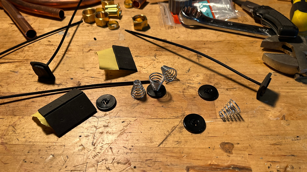
Installation kits designed for electric radiator fans are perfect for this custom work.
After the core was established in space, it was simple to fabricate the pipe and fittings that would exit the core and enter the water separator. To make the turns and bends a little easier, I purchased a very small section of brass pipe, a coupler, and an elbow. This put the cooler exit on the same plane horizontally as the separator, with only one 90 degree vertical bend. Perfect. I reinstalled the tank's outlet pipe, valve, and gauge.
I said a prayer and flipped the switch. It takes several minutes for an empty tank this size to fill up, and in the video we fast forward from time to time. After only a short time of the compressor pump running I noticed I had left my tank drain valve open! No wonder we were not building pressure too well. At about 40 psi on the water separator's gauge I noticed leaks at a couple of places, and that my valve on the separator was not fully open. I tightened these up, the leaks stopped, and water was being collected at the separator. It was truly amazing to feel the difference in heat exchange as I touched both the inlet and the outlet of the cooler's core. I wish I had found my infrared thermometer just to show the results - I will be sure to do so in an upcoming blog post.

Accurate guages are a must - this one was about 10 psi off actual.
The video does a better job in showing what happened next, but suffice to say the loud bang from the inlet pipe was loud enough for Mama to come out of the house to check on me. Essentially, the pipe I decided to reuse to save some time, effort, and cash - it would not hold compression and so the pipe literally popped off the fitting. Of course, we removed the assembly and I fabricated a new pipe and used new fittings. The only other issue experienced was a faulty gauge. The compressor bleeds off air and shuts down the pump at a maximum air pressure of 155 psi. When I was doing the first run up of filling the tank and testing the lines and fitting the gauge I had installed was showing 175 psi when the compressor finally shut off. I replaced that gauge with another used one in my stash, but even that one was off by about 10 psi. Eventually I had to make another run to the home improvement store. This time, I bought a liquid filled gauge - right on the money at 155 psi.
Aftercooler Installation for the Air Compressor
Upcoming Projects
Even though life is throwing us a curveball, I do have some upcoming projects. Some of our subscribers have asked me specific questions so I thought I would use the blog to whet the appetite.
Well now, look what showed up on my front porch!
With my gift certificate from the Fast Fords race in June, I put those Summit bucks towards a carburetor purchase. Over the past several years I have heard good testimonies about these carbs, and of course everyone knows how much the Hot Rod Reverend likes tinkering with carburetors! This one here has been on backorder for over 3 months, so I am thrilled it finally showed. You can expect at least one blog post and a video concerning this carburetor.
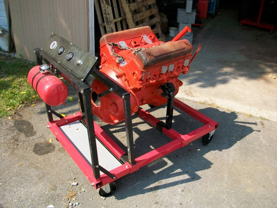
This was my first and only engine run stand that I ever put together. (Larin corporation)
June of 2024 seems like a long time away, but if I am going to successfully bring three engines to the Fords at Carlisle that summer I had better get started. I have a line on some heavy duty 2x4 metal tubing that will not cost me a thing. My plans are to build a base for a truck engine and subsequent bell housing and front mount, giving plenty of options for ram's horns exhaust manifolds and to keep the 90 degree oil filter setup. The other two Y Blocks for display will be on the Larin engine run stand pictured above. I will need to purchase another kit at some point and make the modifications to hold a Y Block. One of my winter projects will be the build of at least one run stand. I may have to make the build into a DIY blog series, who knows?

The Hot Rod Reverend and Bob Martin, race coordinator for the annual Y Block Shootout

When I checked on Bob Martin, I drove the 55 Ford across town to his house.
Several subscribers have been contacting me over the past month asking about Bob Martin. Bob is the race director for the Y Block Shootout each year and writes articles for the Y Block magazine. The reason that people were asking me questions was that no one had heard from Bob for roughly 3 months, and Bob and I happen to live about 15 minutes from each other. I will have to admit, I have been so busy this summer with church ministry in other states, our own move to another house, etc that I had really not been in contact with too many in the hobby anyway. When Bob would not answer my phone calls nor return my voicemails I became concerned as well. I sauntered over to his house one morning and thankfully Bob and his wife answered the door. Bob was recovering from knee surgery and had lost his cell phone a couple of months back! I tried to explain to him how popular he was and how many people were trying to get a hold of him. He kind of chuckled at all of that and promised to make return phone calls as soon as possible. Bob and I did talk Y Blocks for about half an hour. It does look like the Y Block Shootout will take place again on Father's Day weekend, but the days will move to Friday and Saturday, June 16 and 17. We will certainly post more information as we receive it.
The Hot Rod Reverend
aka Daniel Jessup


I would like to add to your interesting contribution the basic diagram of your compressed air installation.
Thank you